23 KiB
| title |
|---|
| New Keyboard Shield |
import Tabs from '@theme/Tabs'; import TabItem from '@theme/TabItem'; import KeymapExampleFile from '../keymap-example-file.md';
Overview
This guide will walk through the steps necessary to add ZMK support for a keyboard the uses a (Pro Micro compatible) addon MCU board to provide the microprocessor. The high level steps are:
- Create a new shield directory.
- Add the base Kconfig files.
- Add the shield overlay file to define the KSCAN driver for detecting key press/release.
- (Optional) Add the matrix transform for mapping KSCAN row/column values to sane key positions. This is needed for non-rectangular keyboards, or where the underlying row/column pin arrangement does not map one to one with logical locations on the keyboard.
- Add a default keymap, which users can override in their own configs as needed.
- Add support for features such as encoders, OLED displays, or RGB underglow.
It may be helpful to review the upstream shields documentation to get a proper understanding of the underlying system before continuing.
:::note ZMK support for split keyboards requires a few more files than single boards to ensure proper connectivity between the central and peripheral units. Check the following guides thoroughly to ensure that all the files are in place. :::
New Shield Directory
:::note
This guide describes how to add shield to the ZMK main repository. If you are building firmware for your
own prototype or handwired keyboard, it is recommended to use your own user config repository. Follow the
user setup guide to create your user config repository first. When following the rest
of this guide, replace the app/ directory in the ZMK main repository with the config/ directory in your
user config repository. For example, app/boards/shields/<keyboard_name> should now be
config/boards/shields/<keyboard_name>.
:::
Shields for Zephyr applications go into the boards/shields/ directory; since ZMK's Zephyr application lives in the app/ subdirectory of the repository, that means the new shield directory should be:
mkdir app/boards/shields/<keyboard_name>
Base Kconfig Files
There are two required Kconfig files that need to be created for your new keyboard
shield to get it picked up for ZMK, Kconfig.shield and Kconfig.defconfig.
Kconfig.shield
The Kconfig.shield file defines any additional Kconfig settings that may be relevant when using this keyboard. For most keyboards, there is just one additional configuration value for the shield itself.
config SHIELD_MY_BOARD
	def_bool $(shields_list_contains,my_board)
This will make sure that a new configuration value named SHIELD_MY_BOARD is set to true whenever my_board is used as the shield name, either as the SHIELD variable in a local build or in your build.yaml file when using Github Actions. Note that this configuration value will be used in Kconfig.defconfig to set other properties about your shield, so make sure that they match.
For split boards, you will need to add configurations for the left and right sides. For example, if your split halves are named my_board_left and my_board_right, it would look like this:
config SHIELD_MY_BOARD_LEFT
	def_bool $(shields_list_contains,my_board_left)

config SHIELD_MY_BOARD_RIGHT
	def_bool $(shields_list_contains,my_board_right)
Kconfig.defconfig
The Kconfig.defconfig file is where overrides for various configuration settings
that make sense to have different defaults when this shield is used. One main item
that usually has a new default value set here is the ZMK_KEYBOARD_NAME value,
which controls the display name of the device over USB and BLE.
The updated new default values should always be wrapped inside a conditional on the shield config name defined in the Kconfig.shield file. Here's the simplest example file.
:::warning The keyboard name must be less than or equal to 16 characters in length, otherwise the bluetooth advertising might fail and you will not be able to find your keyboard from your device. :::
if SHIELD_MY_BOARD

config ZMK_KEYBOARD_NAME
	default "My Board"

endif
Similarly to defining the halves of a split board in Kconfig.shield it is important to set the ZMK_KEYBOARD_NAME for each half of a split keyboard.
You'll also want to set which half is the central side. Most boards set it to the left.
Then on the peripheral half, you'll want to turn USB on so that it shows USB status on displays properly.
Finally, you'll want to turn on the split option for both sides. This can all be seen below.
if SHIELD_MY_BOARD_LEFT

config ZMK_KEYBOARD_NAME
	default "My Board"

config ZMK_SPLIT_ROLE_CENTRAL
	default y

endif

if SHIELD_MY_BOARD_LEFT || SHIELD_MY_BOARD_RIGHT

config ZMK_SPLIT
	default y

endif
Shield Overlays
<Tabs defaultValue="pro_micro" values={[ {label: 'Pro Micro Shields', value: 'pro_micro'}, {label: 'BlackPill Shields', value: 'blackpill'}, ]}>
Pro Micro Shields
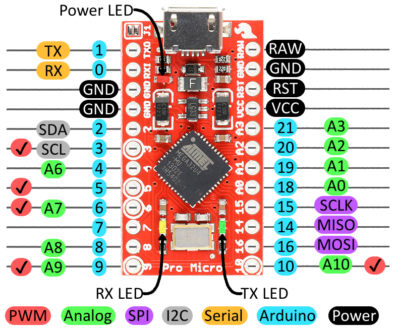
ZMK uses the blue color coded pin names to generate devicetree node references. For example, to refer to the node 0 in the devicetree files, use &pro_micro 0.
BlackPill Shields
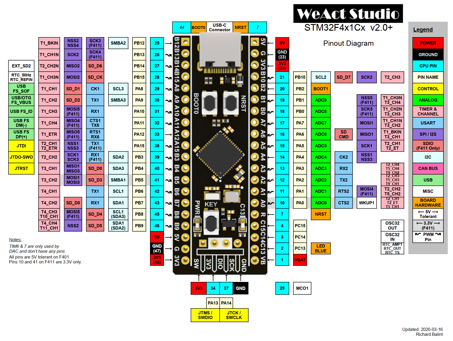
ZMK uses the blue color coded pin names to generate devicetree node references. For example, to refer to the node 17 in the devicetree files, use &blackpill 17.
<Tabs defaultValue="unibody" values={[ {label: 'Unibody Shields', value: 'unibody'}, {label: 'Split Shields', value: 'split'}, ]}>
The <shield_name>.overlay is the devicetree description of the keyboard shield that is merged with the primary board devicetree description before the build. For ZMK, this file at a minimum should include the chosen node named zmk,kscan that references a KSCAN driver instance. For a simple 3x3 macropad matrix,
this might look something like:
/ {
	chosen {
		zmk,kscan = &kscan0;
	};

	kscan0: kscan_0 {
		compatible = "zmk,kscan-gpio-matrix";
		label = "KSCAN";
        diode-direction = "col2row";

        col-gpios
            = <&pro_micro 15 GPIO_ACTIVE_HIGH>
            , <&pro_micro 14 GPIO_ACTIVE_HIGH>
            , <&pro_micro 16 GPIO_ACTIVE_HIGH>
            ;

		row-gpios
			= <&pro_micro 19 (GPIO_ACTIVE_HIGH | GPIO_PULL_DOWN)>
			, <&pro_micro 20 (GPIO_ACTIVE_HIGH | GPIO_PULL_DOWN)>
            , <&pro_micro 21 (GPIO_ACTIVE_HIGH | GPIO_PULL_DOWN)>
			;
	};
};
See the Keyboard Scan configuration documentation for details on configuring the KSCAN driver.
.dtsi files and Shield Overlays (Split Shields)
Unlike unibody keyboards, split keyboards have a core .dtsi file with shield overlays for each half of the keyboard.
It is preferred to define only the col-gpios or row-gpios in the common shield .dtsi, depending on the diode-direction value.
For col2row directed boards like the iris, the shared .dtsi file may look like this:
#include <dt-bindings/zmk/matrix_transform.h>

/ {
	chosen {
		zmk,kscan = &kscan0;
		zmk,matrix_transform = &default_transform;
	};

	default_transform: keymap_transform_0 {
		compatible = "zmk,matrix-transform";
		columns = <16>;
		rows = <4>;
// | SW6  | SW5  | SW4  | SW3  | SW2  | SW1  |                 | SW1  | SW2  | SW3  | SW4  | SW5  | SW6  |
// | SW12 | SW11 | SW10 | SW9  | SW8  | SW7  |                 | SW7  | SW8  | SW9  | SW10 | SW11 | SW12 |
// | SW18 | SW17 | SW16 | SW15 | SW14 | SW13 |                 | SW13 | SW14 | SW15 | SW16 | SW17 | SW18 |
// | SW24 | SW23 | SW22 | SW21 | SW20 | SW19 | SW25 |   | SW25 | SW19 | SW20 | SW21 | SW22 | SW23 | SW24 |
//                      | SW29 | SW28 | SW27 | SW26 |   | SW26 | SW27 | SW28 | SW29 |
		map = <
RC(0,0) RC(0,1) RC(0,2) RC(0,3) RC(0,4) RC(0,5)                 RC(0,6) RC(0,7) RC(0,8) RC(0,9) RC(0,10) RC(0,11)
RC(1,0) RC(1,1) RC(1,2) RC(1,3) RC(1,4) RC(1,5)                 RC(1,6) RC(1,7) RC(1,8) RC(1,9) RC(1,10) RC(1,11)
RC(2,0) RC(2,1) RC(2,2) RC(2,3) RC(2,4) RC(2,5)                 RC(2,6) RC(2,7) RC(2,8) RC(2,9) RC(2,10) RC(2,11)
RC(3,0) RC(3,1) RC(3,2) RC(3,3) RC(3,4) RC(3,5) RC(4,2) RC(4,9) RC(3,6) RC(3,7) RC(3,8) RC(3,9) RC(3,10) RC(3,11)
                        		RC(4,3) RC(4,4) RC(4,5) RC(4,6) RC(4,7) RC(4,8)
		>;
	};

	kscan0: kscan {
		compatible = "zmk,kscan-gpio-matrix";
		label = "KSCAN";

		diode-direction = "col2row";
		row-gpios
			= <&pro_micro 6 (GPIO_ACTIVE_HIGH | GPIO_PULL_DOWN)> // Row A from the schematic file
			, <&pro_micro 7 (GPIO_ACTIVE_HIGH | GPIO_PULL_DOWN)> // Row B from the schematic file
			, <&pro_micro 8 (GPIO_ACTIVE_HIGH | GPIO_PULL_DOWN)> // Row C from the schematic file
			, <&pro_micro 0 (GPIO_ACTIVE_HIGH | GPIO_PULL_DOWN)> // Row D from the schematic file
			, <&pro_micro 4 (GPIO_ACTIVE_HIGH | GPIO_PULL_DOWN)> // Row E from the schematic file
			;

	};
};
:::note
Notice that in addition to the common row-gpios that are declared in the kscan, the matrix transform is defined in the .dtsi.
:::
The missing col-gpios would be defined in your <boardname>_left.overlay and <boardname>_right.overlay files.
Keep in mind that the mirrored position of the GPIOs means that the col-gpios will appear reversed when the .overlay files are compared to one another.
Furthermore, the column offset for the matrix transform should be added to the right half of the keyboard's overlay
because the keyboard's switch matrix is read from left to right, top to bottom.
This is exemplified with the iris .overlay files.
// iris_left.overlay

#include "iris.dtsi" // Notice that the main dtsi files are included in the overlay.

&kscan0 {
	col-gpios
		= <&pro_micro 19 GPIO_ACTIVE_HIGH> // col1 in the schematic
		, <&pro_micro 18 GPIO_ACTIVE_HIGH> // col2 in the schematic
		, <&pro_micro 15 GPIO_ACTIVE_HIGH> // col3 in the schematic
		, <&pro_micro 14 GPIO_ACTIVE_HIGH> // col4 in the schematic
		, <&pro_micro 16 GPIO_ACTIVE_HIGH> // col5 in the schematic
		, <&pro_micro 10 GPIO_ACTIVE_HIGH> // col6 in the schematic
		;
};
// iris_right.overlay

#include "iris.dtsi"

&default_transform { // The matrix transform for this board is 6 columns over because the left half is 6 columns wide according to the matrix.
	col-offset = <6>;
};

&kscan0 {
	col-gpios
		= <&pro_micro 10 GPIO_ACTIVE_HIGH> // col6 in the schematic
		, <&pro_micro 16 GPIO_ACTIVE_HIGH> // col5 in the schematic
		, <&pro_micro 14 GPIO_ACTIVE_HIGH> // col4 in the schematic
		, <&pro_micro 15 GPIO_ACTIVE_HIGH> // col3 in the schematic
		, <&pro_micro 18 GPIO_ACTIVE_HIGH>  // col2 in the schematic
		, <&pro_micro 19 GPIO_ACTIVE_HIGH>  // col1 in the schematic
		;
};
See the Keyboard Scan configuration documentation for details on configuring the KSCAN driver.
.conf files (Split Shields)
While unibody boards only have one .conf file that applies configuration characteristics to the entire keyboard,
split keyboards are unique in that they contain multiple .conf files with different scopes.
For example, a split board called my_awesome_split_board would have the following files:
my_awesome_split_board.conf- Configuration elements affect both halvesmy_awesome_split_board_left.conf- Configuration elements only affect left halfmy_awesome_split_board_right.conf- Configuration elements only affect right half
In most case you'll only need to use the .conf file that affects both halves of a split board. It's used for adding features like deep-sleep or rotary encoders.
// my_awesome_split_board.conf

CONFIG_ZMK_SLEEP=y
:::note
The shared configuration in my_awesome_split_board.conf is only applied when you are building with a zmk-config folder and when it is present at config/my_awesome_split_board.conf. If you are not using a zmk-config folder, you will need to include the shared configuration in both my_awesome_split_board_left.conf and my_awesome_split_board_right.conf files.
:::
(Optional) Matrix Transform
Internally ZMK translates all row/column events into "key position" events to maintain a consistent model that works no matter what any possible GPIO matrix may look like for a certain keyboard. This is particularly helpful when:
- To reduce the used pins, an "efficient" number of rows/columns for the GPIO matrix is used, that does not match the physical layout of rows/columns of the actual key switches.
- For non rectangular keyboards with thumb clusters, non
1ulocations, etc.
A "key position" is the numeric index (zero-based) of a given key, which identifies the logical key location as perceived by the end user. All keymap mappings actually bind behaviors to key positions, not to row/column values.
Without a matrix transform, that intentionally map each key position to the row/column pair that position corresponds to, the default equation to determine that is:
($row * NUMBER_OF_COLUMNS) + $column
Which effectively amounts to numbering the key positions by traversing each row from top to bottom and assigning numerically incrementing key positions.
Whenever that default key position mapping is insufficient, the <shield_name>.overlay file should also include a matrix transform.
Here is an example for the nice60, which uses an efficient 8x8 GPIO matrix, and uses a transform:
#include <dt-bindings/zmk/matrix_transform.h>

/ {
	chosen {
		zmk,kscan = &kscan0;
		zmk,matrix_transform = &default_transform;
	};

	default_transform: keymap_transform_0 {
		compatible = "zmk,matrix-transform";
		columns = <8>;
		rows = <8>;
// | MX1  | MX2  | MX3  | MX4  | MX5  | MX6  | MX7  | MX8  | MX9  | MX10 | MX11 | MX12 | MX13 |    MX14     |
// |   MX15   | MX16 | MX17 | MX18 | MX19 | MX20 | MX21 | MX22 | MX23 | MX34 | MX25 | MX26 | MX27 |  MX28   |
// |    MX29    | MX30 | MX31 | MX32 | MX33 | MX34 | MX35 | MX36 | MX37 | MX38 | MX39 | MX40 |     MX41     |
// |     MX42      | MX43 | MX44 | MX45 | MX46 | MX47 | MX48 | MX49 | MX50 | MX51 | MX52 |       MX53       |
// |  MX54  |  MX55  |  MX56  |                  MX57                   |  MX58  |  MX59  |  MX60  |  MX61  |
		map = <
RC(3,0)  RC(2,0) RC(1,0) RC(0,0) RC(1,1) RC(0,1) RC(0,2) RC(1,3) RC(0,3) RC(1,4) RC(0,4) RC(0,5) RC(1,6)     RC(1,7)
RC(4,0)    RC(4,1) RC(3,1) RC(2,1) RC(2,2) RC(1,2) RC(2,3) RC(3,4) RC(2,4) RC(2,5) RC(1,5) RC(2,6) RC(2,7)   RC(3,7)
RC(5,0)     RC(5,1) RC(5,2) RC(4,2) RC(3,2) RC(4,3) RC(3,3) RC(4,4) RC(4,5) RC(3,5) RC(4,6) RC(3,6)          RC(4,7)
RC(6,0)       RC(6,1) RC(6,2) RC(6,3) RC(5,3) RC(6,4) RC(5,4) RC(6,5) RC(5,5) RC(6,6) RC(5,6)                RC(5,7)
RC(7,0)    RC(7,1)   RC(7,2)                     RC(7,3)                    RC(7,5)    RC(7,6)    RC(6,7)    RC(7,7)
		>;
	};
Some important things to note:
- The
#include <dt-bindings/zmk/matrix_transform.h>is critical. TheRCmacro is used to generate the internal storage in the matrix transform, and is actually replaced by a C preprocessor before the final devicetree is compiled into ZMK. RC(row, column)is placed sequentially to define what row and column values that position corresponds to.- If you have a keyboard with options for
2ukeys in certain positions, or break away portions, it is a good idea to set the chosenzmk,matrix_transformto the default arrangement, and include other possible matrix transform nodes in the devicetree that users can select in their user config by overriding the chosen node.
See the matrix transform section in the Keyboard Scan configuration documentation for details and more examples of matrix transforms.
Default Keymap
Each keyboard should provide an OOTB default keymap to be used when building the firmware, which can be overridden and customized by user configs. For "shield keyboards", this should be placed in the app/boards/shields/<shield_name>/<shield_name>.keymap file. The keymap is configured as an additional devicetree overlay that includes the following:
- A node with
compatible="zmk,keymap"where each child node is a layer with abindingsarray that binds each key position to a given behavior (e.g. key press, momentarily layer, etc).
Here is an example simple keymap for the Kyria, with only one layer:
:::note
The two #include lines at the top of the keymap are required in order to bring in the default set of behaviors to make them available to bind, and to import a set of defines for the key codes, so keymaps can use parameters like N2 or K instead of the raw keycode numeric values.
:::
Keymap Behaviors
Further documentation on behaviors and bindings is forthcoming, but a summary of the current behaviors you can bind to key positions is as follows:
kpis the "key press" behavior, and takes a single binding argument of the key code from the 'keyboard/keypad" HID usage table.mois the "momentary layer" behavior, and takes a single binding argument of the numeric ID of the layer to momentarily enable when that key is held.transis the "transparent" behavior, useful to be place in higher layers abovemobindings to be sure the key release is handled by the lower layer. No binding arguments are required.mtis the "mod-tap" behavior, and takes two binding arguments, the modifier to use if held, and the keycode to send if tapped.
Metadata
ZMK makes use of an additional metadata YAML file for all boards and shields to provide high level information about the hardware to be incorporated into setup scripts/utilities, website hardware list, etc.
The naming convention for metadata files is {item_id}.zmk.yml, where the item_id is the board/shield identifier, including version information but excluding any optional split _left/_right suffix, e.g. corne.zmk.yml or nrfmicro_11.zmk.yml.
Here is a sample corne.zmk.yml file from the repository:
file_format: "1"
id: corne
name: Corne
type: shield
url: https://github.com/foostan/crkbd/
requires: [pro_micro]
exposes: [i2c_oled]
features:
  - keys
  - display
siblings:
  - corne_left
  - corne_right
You should place a properly named foo.zmk.yml file in the directory next to your other shield values, and fill it out completely and accurately. See Hardware Metadata Files for the full details.
Adding Features
Encoders
EC11 encoder support can be added to your board or shield by adding the appropriate lines to your board/shield's configuration (.conf), device tree (.dtsi), overlay (.overlay), and keymap (.keymap) files.
<Tabs defaultValue="conf" values={[ {label: '.conf', value: 'conf'}, {label: '.dtsi', value: 'dtsi'}, {label: '.overlay', value: 'overlay'}, {label: '.keymap', value: 'keymap'}, ]}>
In your configuration file you will need to add the following lines so that the encoders can be enabled/disabled:
# Uncomment to enable encoder
# CONFIG_EC11=y
# CONFIG_EC11_TRIGGER_GLOBAL_THREAD=y
These should be commented by default for encoders that are optional/can be swapped with switches, but can be uncommented if encoders are part of the default design.
:::note If building locally for split boards, you may need to add these lines to the specific half's configuration file as well as the combined configuration file. :::
In your device tree file you will need to add the following lines to define the encoder sensor:left_encoder: encoder_left {
compatible = "alps,ec11";
label = "LEFT_ENCODER";
a-gpios = <PIN_A (GPIO_ACTIVE_HIGH | GPIO_PULL_UP)>;
b-gpios = <PIN_B (GPIO_ACTIVE_HIGH | GPIO_PULL_UP)>;
resolution = <4>;
};
Here you will have to replace PIN_A and PIN_B with the appropriate pins that your PCB utilizes for the encoder(s). For keyboards that use the Pro Micro or any of the Pro Micro replacements, Sparkfun's Pro Micro Hookup Guide has a pinout diagram that can be useful to determine the right pins. Reference either the blue numbers labeled "Arduino" (digital pins) or the green numbers labeled "Analog" (analog pins). For pins that are labeled as both digital and analog, refer to your specific board's .dtsi file to determine how you should refer to that pin.
Add additional encoders as necessary by duplicating the above lines, replacing left with whatever you would like to call your encoder, and updating the pins. Note that support for peripheral (right) side sensors over BLE is still in progress.
Once you have defined the encoder sensors, you will have to add them to the list of sensors:
sensors {
		compatible = "zmk,keymap-sensors";
		sensors = <&left_encoder &right_encoder>;
	};
In this example, a left_encoder and right_encoder are both added. Additional encoders can be added with spaces separating each, and the order they are added here determines the order in which you define their behavior in your keymap.
Add the following lines to your overlay file(s) to enable the encoder:&left_encoder {
status = "okay";
};
:::note For split keyboards, make sure to add left hand encoders to the left .overlay file and right hand encoders to the right .overlay file. :::
Add the following line to your keymap file to add default encoder behavior bindings:sensor-bindings = <&inc_dec_kp C_VOL_UP C_VOL_DN>;
Add additional bindings as necessary to match the default number of encoders on your board. See the Encoders and Keymap feature documentation for more details.
Testing
Once you've fully created the new keyboard shield definition, you should be able to test with a build command like:
west build --pristine -b proton_c -- -DSHIELD=my_board
The above build command generates build/zephyr/zmk.uf2. If your board
supports USB Flashing Format (UF2), copy that file onto the root of the USB mass
storage device for your board. The controller should flash your built firmware
and automatically restart once flashing is complete.
Alternatively, if your board supports flashing and you're not developing from within a Dockerized environment, enable Device Firmware Upgrade (DFU) mode on your board and run the following command to test your build:
west flash
Please have a look at documentation specific to building and flashing for additional information.
:::note
Further testing your keyboard shield without altering the root keymap file can be done with the use of -DZMK_CONFIG in your west build command,
shown here
:::